In my last medium article, I wrote about quantum computers based on ion traps, their appeal, and shortcomings. You might remember that they require extreme cooling and are prone to noise and decoherence. These hindrances are due to unwanted interactions among the ions themselves or with the confining electromagnetic fields — this sounds like a line from a Marvel movie.
The unwanted interactions are due in part to their being electrically charged. To avoid it, we could use neutral particles, such as Rydberg atoms, which respond strongly to applied external fields, or photons, the particles that constitute light. Here, as you might have guessed, we will choose photons. In my next articles I might cover Rydberg atoms, which are just as cool as ions. ba-dum tssss!
It is hard to overstate how interesting photons are. Their mix of quantum properties and relativistic nature has motivated a complete overhaul of our understanding of the universe in the last century. Moving with the speed of light (duh!), they are massless particles that carry linear momentum, which means they can flick electrons out of an atom. If you think about it, this is already at odds with our classical, a.k.a Newtonian, world view; imagine yourself trying to play billiards with a massless cue ball.
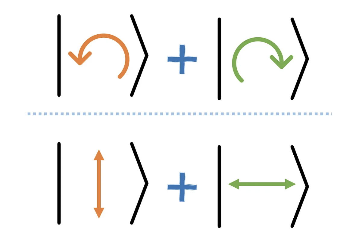
Like collective light, individual photons have polarization. This characteristic, in their case, acquires quantum properties of superposition and entanglement. For example, they can be plane- (vertical — horizontal) or circular- (clockwise — counter-clockwise) polarized. This means we can use these configurations to map the classical bits 0 and 1. But that is not all there is to photons!
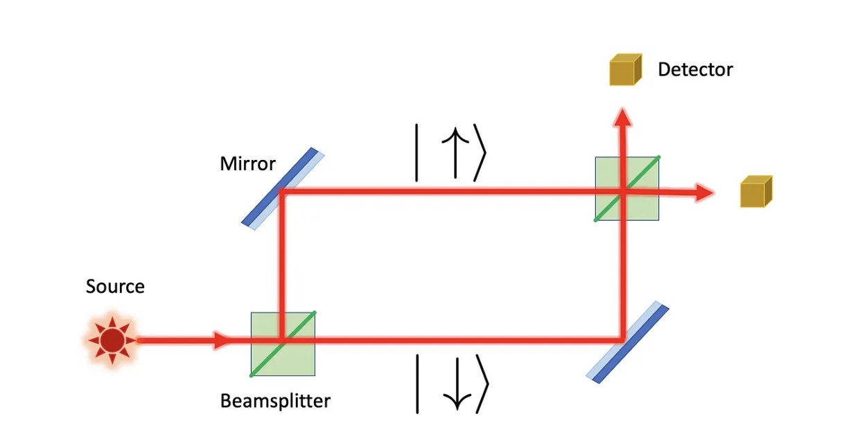
In interferometers, such as the Mach-Zehnder type, the photon can be put in a superposition of different paths. Think of Young’s double-slit experiment. This is actually closer to the qubit implementation we will use throughout this article.
Using photons is advantageous as they do not require such careful cooling as other quantum computer technologies, but also because several high-quality photonics components (such as low-loss optical fibers, phase-shifters, and beamsplitters) are already produced at industrial scale [1].
Encoding bits
The most natural choice of qubit, at least for me, is the polarization. We can simply label clockwise/horizontal as 0 and counter-clockwise/vertical as 1, depending on the basis we choose. By manipulating the relative phase between the electric and magnetic fields, we can create superpositions of different polarizations. But what about entanglement? Well, that takes me back to the experiments carried out by last year’s Nobel laureate Alain Aspect and his colleagues J. Dalibard and G. Roger [2].
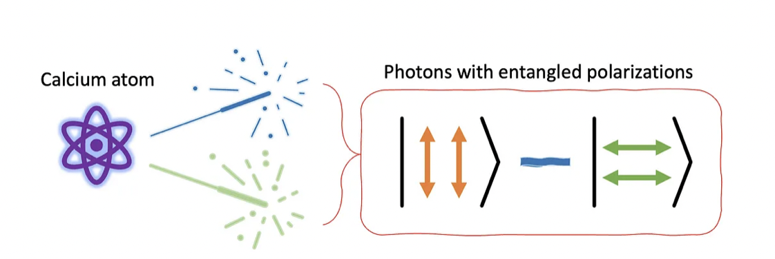
By exciting a calcium atom in a particular way, they produced photon pairs with entangled polarization states to test Bell’s inequality [3]. The results have shown a clear match between the experiment and the predictions of quantum mechanics. But alas! Polarization will not be the qubit representation we will use, but I hope the short historical detour was worth it. We will instead use the so-called dual-rail representation.
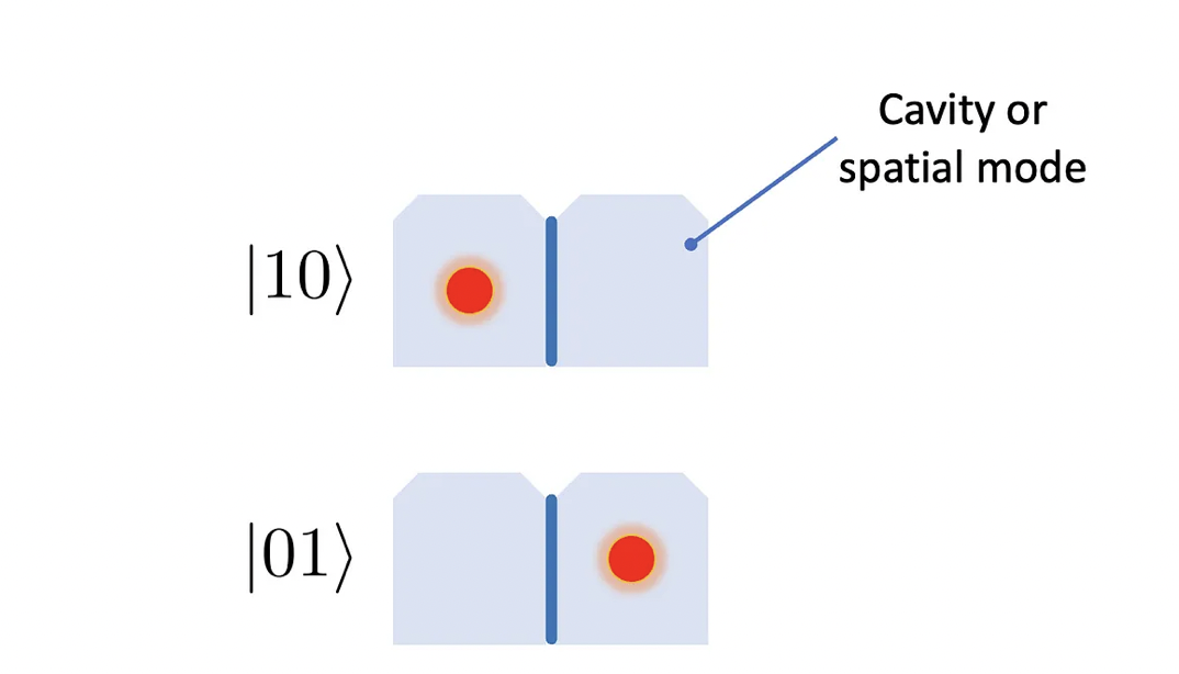
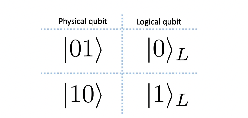
Each photon carries an amount of energy equal to ℏω (the funny h, or h-bar, is just the Planck’s constant divided by 2π, while ω is the angular frequency of the corresponding electromagnetic wave). These photons can be put in one of two available cavities, like in the drawing above.
Given these mutually exclusive (orthogonal) configurations, a superposition would then be written as a|01> + b|10>. Despite this picture of cavities, try to imagine the single photons traveling in different spatial modes as wavepackets along the circuit components. In an interferometer, for example, these spatial modes correspond to different paths the photon is allowed to take.
Generating single photons
Well, I will tell you in advance that it is not easy. For instance, in an ion trap, you can set the ions in place and cool them to initialize the quantum register in a certain state. Photons cannot be trapped as easily, and measuring their state means destroying them (it sounds very dramatic, I prefer calling it an absorption). Here we will see two ways of creating single photons.
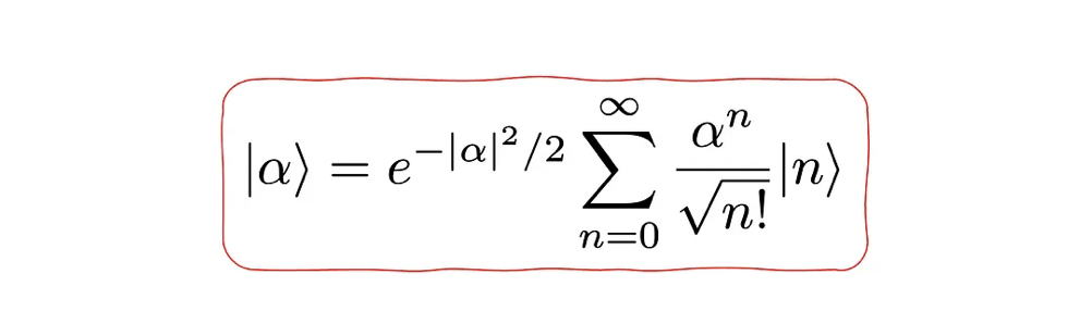
The first method is by attenuating a laser. The idea is very simple, do not be intimidated by the expression above, it just represents the quantum state a laser outputs. The idea of attenuating a laser makes more sense once we acknowledge the laser’s mean energy: <α|n|α> = |α|², where n is the number operator (it counts how many photons the quantum state contains). Accordingly, by making α smaller, the number of emerging photons is reduced. Observe that, if we set α = √0.1, there is a 90% probability that no photons will come out. But if light emerges from the attenuator, in 95% of the times it will be as single photons, implying a 5% chance of failure.
A problem with this method is that there is no way of knowing (with certainty) in advance how many photons were output, given that the state is a superposition. Another is that they cannot be synchronized, which poses a big problem if you want to build a quantum register with multiple qubits. These issues can be lessened by using parametric downconversion, the second method we will cover.
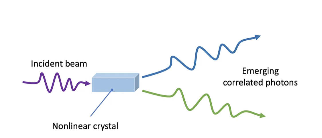
Some nonlinear crystals are optically active and exhibit fascinating phenomena, such as parametric downconversion. Here is how it works: an incident photon interacts with the crystal and causes an excitation that triggers an spontaneous emission of a pair of correlated photons. Their correlation means their momenta, energy, and polarization are linked, i.e., entangled.
For this reason, they are also called a biphoton, or twin photons. By measuring one of them (destroying or absorbing it) with a certain energy and polarization, we are sure to have another photon with the complementary properties. This method provides a better way to synchronize photons, as the outputs of multiple downconversions can be delayed to fit in the resolution of the gates and detectors. But speaking of equipment, it is time to talk about the most important components of photonics-oriented quantum circuits.
Equipment for manipulating photon states
The first element we need are mirrors, so we can guide the photons throughout the experiment. Luckily, it is fairly common to find excellent mirrors with losses in the order of fractions of a percent. That is not the case with nonlinear media, which we will talk about later.
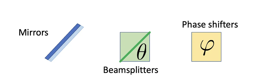
Second, we need phase shifters. Their name comes from the relative phase shift they provide when light goes through media with different refraction indices. For example, if two identical beams are separated and go through media with refractive indices n₀ and n₁ (like air and common borosilicate glass, for which n₁ = 1.5 n₀), they will acquire a relative (complex) phase of φ = exp(i(n₁-n₀)Lω/c₀), where L is the distance traveled, ω the light’s frequency, and c₀ is the speed of light in vacuum.
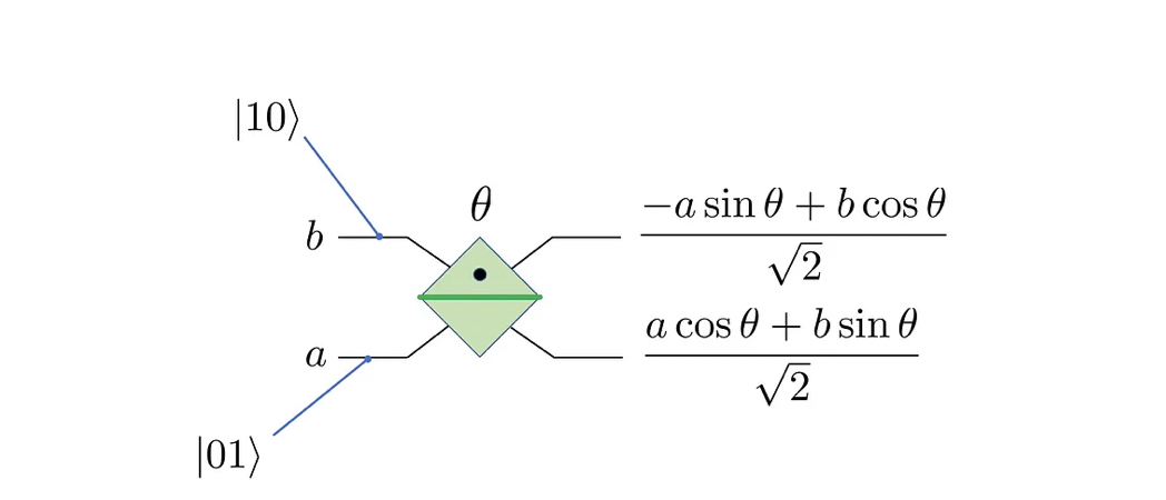
Next, we need beamsplitter. As the name implies, it splits incoming light. It does so via semi-transparent mirrors. Below is a sketch of it in the dual-rail representation. The parameters a and b represent the amplitudes in the state a|01> + b|10>. In addition, the main characteristic of a beamsplitter is the fraction R of light it reflects, which we will encode in an angle as cosθ = R.
The last and most elusive component requires media with nonlinear optical properties, namely the optical Kerr effect. In such media, the refraction index (and the corresponding phase shift) depends on the intensity I of incident light as: n(I) = n + n₂(I). The key idea is the following: if two beams of equal intensity I go through a length L of such medium, both will acquire a relative phase exp(iLn₂Iω/c₀) compared to the case with a single beam. Ideally we could adjust the length L at will, but unfortunately the probability of the photon being absorbed is very high. Now that we have all elements, let us see how to use them to build a universal gate set.
Building universal gate sets
We will follow the steps of my last Medium article, that is, z- and y-rotations, followed by a controlled phase-flip. Because the connection between physical and logical qubits is not as evident as in the case of trapped ions, I will focus on the operations on the lowest level, that is, on the physical qubits.
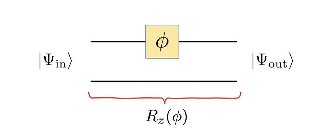
For the z-rotation, it suffices to place a phase shifter in one of the photon spatial modes, that is, in one of the lines of the dual rail representation, as shown below. Except for a global phase, the effect of it is transforming the state a|01> + b|10> into a.exp(-iφ/2) |01> + b.exp(+iφ/2)|10>, which matches what you would expect from a z-rotation. The phase φ depends on the component’s length L, the difference between the refraction indices n₁-n₀, the frequency ω and speed of light in vacuum c₀.
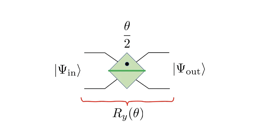
The beamsplitters provide us with the y-rotations. By the way, the Hamiltonian that models its functioning requires defining creation and annihilation operators, which I will not show here, although there is a very cool mapping between them and the Pauli matrices [see Ref. 1 — box 7.3]. A similar procedure, the Jordan-Wigner transformation, is needed when transforming a molecular Hamiltonian (written in terms of creation and annihilation operators) into a spin Hamiltonian (which can be implemented on a typical quantum register). This translation is very important in the variational quantum eigensolver. But I digress here; the effect of the beamsplitter in each mode matches that of a y-rotation, as shown below.
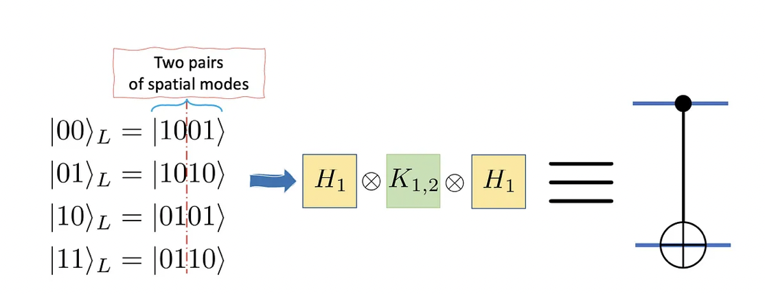
With the operations above, one can create any single-qubit operation, including a Hadamard gate (H). That means we are only missing an entangling operator, such as the controlled-not operator. In that case, we need 2 logical qubits, that is, two pairs of modes. The effect of the nonlinear Kerr medium is fundamental here, as it does the following to each possible mode:
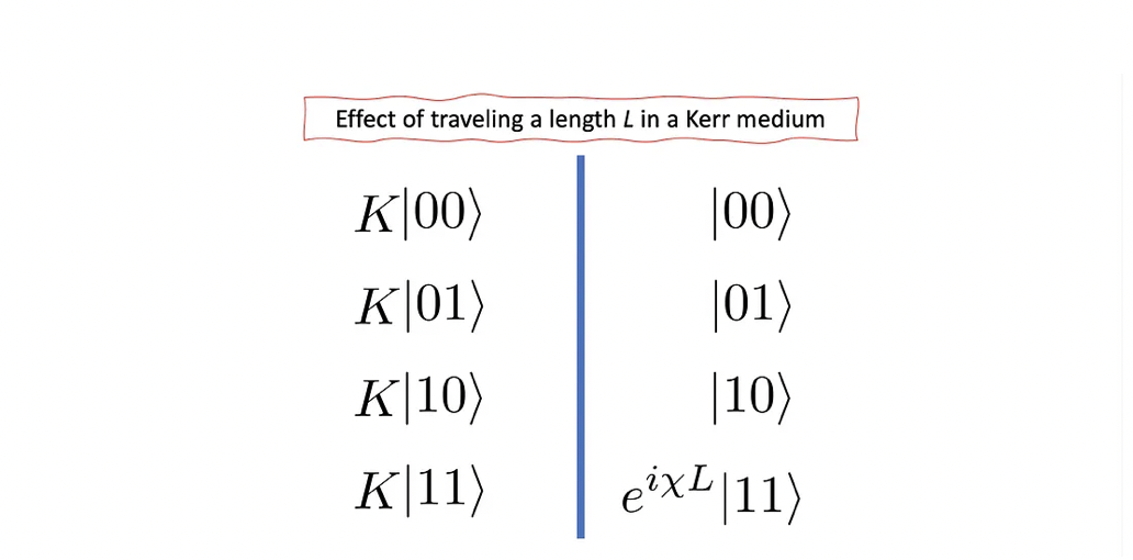
By using two logical qubits, we can build a controlled-not operator via the following mapping:
Excellent! With these we are able to build any state we want. Well, in theory… I say that because many difficulties stand in the way, as hinted above. Examples of it are single-photon production, synchronisation, and weak Kerr media available. Regarding the latter, they are weak in the sense they are not enough to flip the phase of the state |11>; if you try it, there is roughly a 98% chance of the photon being absorbed.
Despite these drawbacks, photons are already used in quantum cryptography and are natural candidates for communication between quantum computers, as pointed out by Olivier Ezratti (check his blog and book in the hyperlink). Meanwhile, the search for better nonlinear optical media continues.
At ColibrITD we choose the best hardware available for our customers’ use case. That requires familiarity with the underlying technology and peculiarities of each machine.
References
[1] Michael A. Nielsen, and Isaac L. Chuang. Quantum Computation and Quantum Information: 10th Anniversary Edition. Cambridge University Press. Cambridge, 2010.
[2] Alain Aspect, Jean Dalibard, and Gérard Roger. Experimental Test of Bell’s Inequalities Using Time-Varying Analyzers. Phys. Rev. Lett. 49, 1804 (1982).
[3] On the Einstein Podolsky Rosen paradox. J. S. Bell. Physics Physique Fizika 1, 195 (1964).
Discover the Latest Blog Posts
Experience FASTER and More Efficient Computing with Our Quantum Solution


